What Should I Look for in an Angle Roll?
Quantum Machinery Group provides a general overview of angle roll machines and how to choose the right one for your metal fabrication or machine shop business.
Angle rolls, also known as profile rolls, section rolls, or simply “rollers,” are all names used for the machines metal fabricators use to make round bends in metal profiles. These rolling machines play a very important role in metal fabrication, and knowing what to look for when selecting an angle roller is essential to the success of a given task.
Let’s take a look at how these machines work, what makes the different varieties of rollers different, and how one should select the appropriate roller for the job they have in mind.

Angle Roll Overview
Angle rolls are very common machines in environments where metal profiles need to be formed to a specific radius or diameter. Angle iron, solid square, solid rectangle, round tubing, and pipe are the most common type of profiles used with this type of equipment.
Because of the wide variety of metals needing to be shaped, and the even wider variety of tasks requiring shaped metal, the fabrication market is full of different varieties of rolling machines, each with its own strengths, weaknesses, and particular uses.
One example of the differences between different angle rolls is capacity. Each rolling machine will be rated according to its strength yield. As an example, rolling machines used to shape plate metal will typically have a yield strength of between 36,000 and 38,000 pounds per square inch (PSI).
Steel mills, on the other hand, often handle metal profiles that require between 48,000 and 58,000 psi. An angle roll that works perfectly well in one environment may not meet the requirements of another.
Another difference between rolling machines is the number of rolls it has. The rolls are the round, spinning parts of the angle roll that allow it to do its job. Every angle roll comes with at least one pinching roll, which is the roll that holds the metal in place and allows it to be fed through the machine. Plate rolling machines come in one or two varieties: single-pinch and double-pinch, referring to how many pinching rolls it has.
Pressing roles, on the other hand, are the part of the machine that does the actual bending. Here there are even more varieties than with pinching roles. Examples of different types of rolling machines based on the number of pressing roles include three-roll double-pinch, four roll double-pinch, three-roll initial pinch, and more.

When determining which rolling machine is best suited for the task one has at hand, it is important to research what each rolling machine is designed to do, and to understand the materials that one will be working with. Manufacturers can usually provide detailed information about their machines, such as capacity and yield.
Compare the manufacturer’s information about how much force a machine can produce and what kind of metals (sheet, roll, etc.) it is designed to handle, and compare this to your site’s mill certificates or other relevant information to see which angle roll best fits your needs.
Want to find out more information about angle rolls and their uses? Contact Quantum Machinery today at 909-476-8007.
Why You Need to Keep Your Metalworking Machine Manuals
Before tossing out the owner's manual that came with your metalworking machine, read this post from Quantum Machinery Group to see why you need to keep it.
Most of us throw away the instruction manual when we buy a new product. Sometimes, we like the challenge of doing it ourselves; other times, we already know how the item works and don’t need to read the same book twice. This works fine for simpler things like vacuum cleaners and bookshelves, but not for more complex machinery. When it comes to advanced equipment, like press brakes and metal benders, it’s very important to keep the manuals somewhere safe and accessible for future reference.

Specifics
Saving manuals is especially crucial for high-tech industrial equipment like machines and devices used in metalworking. In many ways, it’s just as important as saving a vehicle’s manual written by and for mechanics. There’s too many specifics that vary from car to car to keep track of in your head. If you’re doing that, then you may as well memorize an encyclopedia.
These manuals show you the specifics on how to operate the machine in question. They will include the specific numbers needed for settings, ranges, thresholds, and limitations, how to program it, and how to troubleshoot it if it breaks. It’s nearly impossible to remember and quickly recall this information on your own. This is especially true for metal bending because most bending machinery is heavily reliant on brand-specified numbers.
Diagrams
Machine manuals also contain detailed diagrams that explain the inner workings of the machine itself. Most shops just don’t have the time to reverse engineer or perform an autopsy on a machine when it breaks, especially if the shop didn’t create the machine in the first place. Having access to these diagrams solves problems so much faster.
Breakdowns and Troubleshooting
Every machine suffers from wear and tear. Eventually, the parts inside of it will break down. The parts that go into most metalworking machinery are highly specific and calculated in design, so it isn’t as easy as ordering them from Amazon. You won’t find them at your local hardware store, and you need to know the reference numbers for the manufacturer parts you’re looking for. Your machine manual contains all of this information, and much more, saving you time and reducing the headache of guessing what parts you need.
Compatibilities
Your machine manual will also tell you what type of materials your equipment can handle and to what extent it can be pushed. Metalworking requires precise calculations by its nature, so winging it and experimenting with non-compatible equipment is incredibly unsafe. Simply put: It’s safer for your entire shop to consult the manual before using equipment dangerously and causing an accident.
Show, Don’t Tell
Sometimes, it’s easier to show something than it is to describe it. This is especially true when talking to someone over the phone or writing an email where you can only use words. You can use the manual and make a scan of the specific page in the manual that you need and fax or email it the person you’re working with. This also allows you to draw or circle something on the copy without damaging the original, making it easier to communicate broken press brakes or machine failures to repair specialists from a distance.
Missing a machine manual? Need to find press brakes for sale? Quantum Machinery can help. Contact us today for all of your most important metalworking needs.

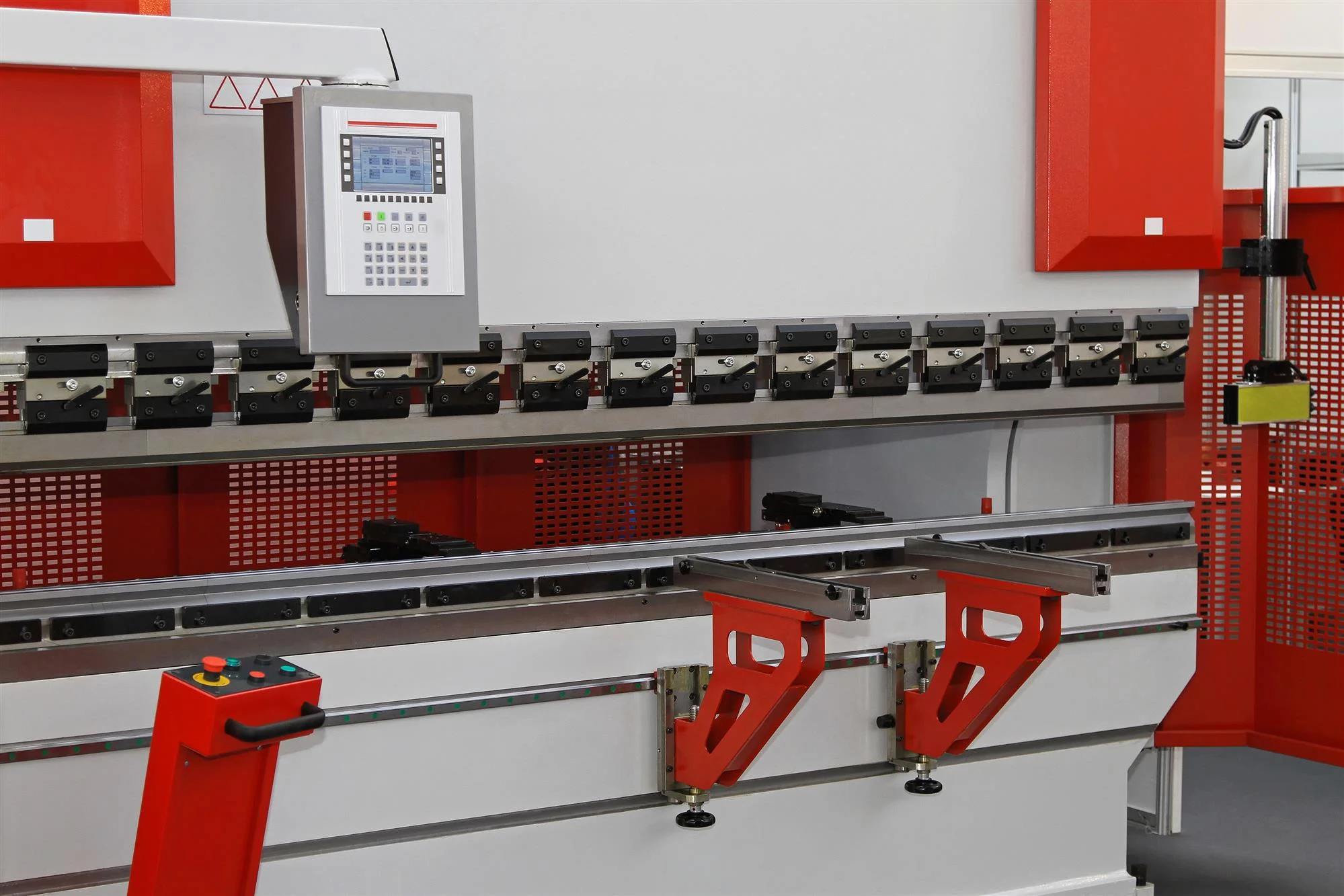
How to Achieve a Perfect Press Brake Bend
Having difficulties getting that "perfect" press brake bend? Check out this blog from Quantum Machinery Group for steps on getting the best bending results.
Bending metal requires high-tech equipment and a very methodical approach. The steps are linear in nature and cannot be skipped without resulting in failure. Each step of using a press brake depends on the ones before it to achieve success. Use these steps to help you get the metal bend you’re looking for when using press brakes.
Know Your Materials
Different metals have different properties that determine how they react to stress. Metals will naturally bend back closer to their original shape when force is applied to them. Some metals need to be bent more than others to achieve the same end result. Metal also stretches when bent and at different rates, depending on the material. The measurements of the bend are typically determined by the type of metal being used, its thickness, and the shape of the die it is being pressed against.
Create a Drawing
Create a drawing of your desired bend by determining the shape of the bend you want and the materials being used. You can reference drawings from previous runs, if needed, but make sure the new bend is factually correct and consistent.
Select the Bending Method
Choosing the right bending method that’s most appropriate for the bend you want is vital. Most bending methods are very similar to each other, but they do have slight differences. Be sure the details of your plans will work with the method you choose.
Calculate Tonnage
Once you know your bend, calculate the tonnage needed for the bend based on the material, the bend you want, and the bending method being used. There are tonnage charts readily available to search for if there isn’t already one nearby the equipment you’re using.
Assess Tooling Position
Assess the tooling position of your material on the bend. If you find you need more tonnage than the machines concentrated load limit, then you can still do the bend, but it will have to be off-center. Check the press machine being used to see if it allows off-center loading and the limitations it can handle. It’s possible to finish the job by using these off-center guidelines, but it’s not safe to exceed them.
Install the Right Tooling
Install the correct tooling for the job. Once you’ve made the calculations, it’s time to set up the machine itself. This is typically the most time-consuming part of the process, so it’s important to make sure your numbers and processes are accurate. Manually setting up the various parts will vary slightly from machine to machine. Ask a press brake operator or consult the manual if you aren’t sure how to properly set up the machine.
Enter Your Calculations
Input the calculations into the press brake machine. This step highly depends on the machine you are using. Older machines may require some manual programming while newer ones have many things pre-configured.
Test Your Bend
Do a test run! Make sure everything’s good to go before doing a mass production run. If something doesn’t line up, go back to the previous steps and find the problem.
Keep in mind that some parts will have imperfections when you start your mass production. This is expected, and you should do some post-run testing to make sure the products meet your standards. If you need help choosing press brakes, feel free to contact the team at Quantum Machinery today.

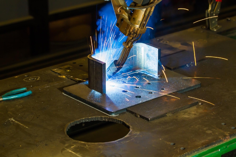
Tips for Choosing Welding Tables
Are you in need of a new welding table and not sure what is best for your business? Read this blog from Quantum Machinery Group for some great buying tips.
Getting the right welding table is a significant component of having a successful shop. You don’t want a table that is difficult to use and understand, nor do you want one that’s filled with poor materials of subpar quality. Quantum Machinery Group offers welding tables that are far above the competition in durability, quality, reliability, and ease of use. Choose from options like steel saw blades, circular saws, table band saws and more to ensure that you have a table that lets you work smarter, not harder.
Not sure where to start? We’ve put together a handy guide that will help you identify your needs and find the best solution for your shop. It’s that easy!
Why Not Build One Yourself?
Some welders think they can just build a table for themselves. While this isn’t technically impossible, and experienced welders may very well be able to accomplish the task, many others do not have the time or right state of mind to get the job done.
So much work goes into creating a sturdy welding table. You’ll need to consider high load capacity, level surface, and high resistance against stroke impact. Self-builders spend a considerable amount of time working to get the table right, and that time investment can end up being sub-par when compared with purchasing a new table outright.
Why Not Go with a Different Manufacturer?
Plenty of manufacturers are available to make welding tables, so why not go with one of them? Quantum Machinery focuses on the customer. We want to provide high-quality, professional welding tables to you so you can have premium steel options for a high workload. Other manufacturers focus on creating colorful tables that catch people’s eyes. These are fun to look at, but they may not hold as much weight or be as level as they need to be.
The Quantum Machinery Group’s Welding Table Options
All of our tables are made of premium steel. They are plasma-nitrided and coated for maximum durability and longevity. This results in a wear-free, corrosion-resistant surface that resists stroke impact or damage. We also offer a diagonal grid with bored holes for further flexibility or additional clamping options—something many other tables just don’t have. You can choose a 16mm welding table or 28mm welding table, depending on your size requirements.
Need enhanced options? Table kits may be the answer. The System 16 and System 28 welding table sets come with all of the most common accessories you need to use the table to the best of your ability. Clamps, squares, stops, and bolts—it’s all packed in when you purchase for an easy setup.
In addition, we have various kits that feature a variety of items that will make your daily job tasks much easier.
Work smarter (not harder) with a Quantum Machinery welding table. These tables have everything you need to meet your welding requirements and can handle a high capacity on your busiest workdays. Find the best table for your needs by contacting us today for a quote.

Technology Spotlight: Modular design meets the press brake
Quantum Machinery Group shares a blog about how the "multi-frame" approach can reduce the mass tonnage of machines in this technology spotlight series post.
"Multi-frame" approach reduces the mass of high-tonnage machines
Originally published in The Fabricator in March 2017. Written by Tim Heston.
A press brake manufacturer uncovers an alternative to the conventional C-frame design. According to the company, the modular design eliminates the need for a conventional crowning system and makes machine installation easier.
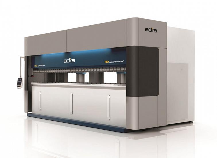
The HD Greenbender has a modular design that accounts for deflection using supplementary hydraulics instead of a conventional crowning system.
It’s a big leap for a heavy or an industrial fabricator to invest in a massive press brake. It can give a shop some bragging rights, for sure, but installing such massive machines can be arduous affairs. They require foundation work (pit installation), and they aren’t the easiest to transport.
Big press brakes are big for a reason. Such monster machines exert tremendous force, so engineers add mass to the machine frame to deal with that force. The machine frame deflects, hence the need for crowning devices integrated into the brake’s lower beam.
But recently engineers at Portuguese machine tool manufacturer Adira Metal Forming Solutions S.A. developed a way to deal with such force in a different way. According to the company, the approach, designed into its HD Greenbender line, eliminates the need for pit installations by lowering the overall mass of the machine and making the design modular. And as the company explained, the machine has no need for a conventional crowning system.
Most press brakes are built using a C-frame, with two side housings and two beams, one fixed (usually the bottom beam) and one moving. The new approach uses a T-frame, not just on either side of the brake but also spaced evenly across the press brake’s width. The company calls this its “dematerialized” approach.
As Rui César, project applications manager, explained, “On a normal press brake, the bending is supported by the C-frame, which deflects upward when the cylinders are actuating. In this system, since the frame was dematerialized, we cannot use the same strategy, which could compromise structural integrity.
“Since we use different structural modules,” César continued, “we have several support points. Instead of having two lateral C-shaped frames and a central beam, we place intermediate supports. This allows us to minimize deformation. And the distance between frames, which can be critical on long machines, doesn’t present a problem.”
Adira calls this a “multi-frame” design. The space behind the tooling isn’t open. Instead, the T-frames across the machine introduce a throat depth across the bed, like a tandem or triplet machine. Still, sources emphasized that this is not a tandem or triplet system, but instead one machine with one upper and lower beam. Regardless, sources said that the T-frame allows machines to be designed with a very deep throat depth between the tooling and the pillar of the T-frame behind it (see photo).
“The modules are topographically optimized to their size and required loads,” César said. “If a different [open] height or [throat] depth is needed, the same compensation concept may be used, but it would require a new structure.” Using software, engineers can run simulations and tailor the design around a specified throat depth, as well as open height and stroke depth.
On each T-frame are two hydraulic cylinders, one in front and one at the rear of the machine. The two cylinders work in concert and, by doing so, can exert bending force while also compensating for deflection. This, sources said, eliminates the need for a conventional crowning system.
“The rear hydraulic actuator applies an upward force, hence compensating for the normal deflection of the structure,” César said.
“When the main cylinder exerts force, the rear cylinder compensates for deflection and keeps the system balanced. There is also dynamic control between the two [cylinders], using electronic control with sensors.”
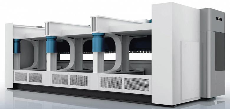
Each T-frame is part of a module that includes a hydraulic cylinder in the front and (as shown in blue) in the back.
Last year the company introduced a 750-ton prototype, with each of the machine’s three cylinders applying 250 tons of forming force. “The total force will be proportional to the number of modules that you use,” said Filipe Coutinho, product development engineer.
“We can go up to 500 tons with each frame,” César said. Each T-frame is part of a module, and if a machine uses six modules, each exerting 500 tons, the machine would have a total tonnage of 3,000 tons. César added that the limitations would involve the dimensions and weight for transport.
Regardless, they said that the approach may open up the potential for heavy forming to more fabrication facilities, with smaller, manageable modules arriving on-site and then assembled together into a machine that, ultimately, can bend seriously thick plate.